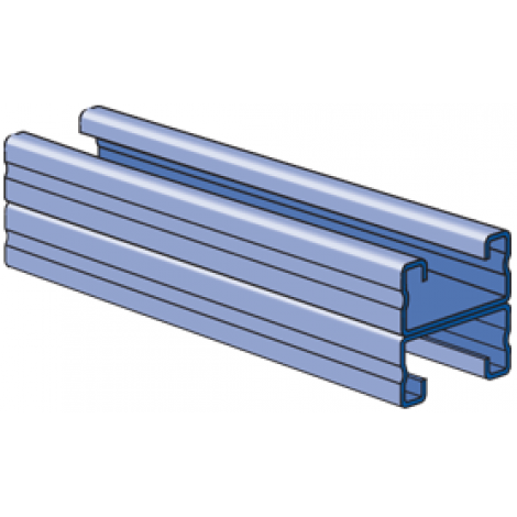
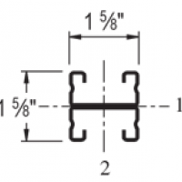
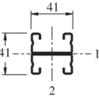
| Elements of Section - P4001 | ||
| Area of Section | 0.487 in2 (3.1 cm2) | |
Axis 1-1 | Axis 2-2 | |
| Moment of Inertia (I) | 0.104 in4 (4.3 cm4) | 0.183 in4 (7.6 cm4) |
| Section Modulus (S) | 0.128 in3 (2.1 cm3) | 0.225 in3 (3.7 cm3) |
| Radius of Gyration (r) | 0.462 in (1.2 cm ) | 0.613 in (1.6 cm ) |
| ||||||||||||||||||||||||||||||||||||||||||||||||||||||||||||||||||||||||||||
| Beam Loading - P4001 | ||||||
| Span (in) | Max Allowable Uniform | Defl at Uniform load (in) | Uniform Loading at Deflection | Lateral Bracing Reduction Factor | ||
| Span /180 (lbs) | Span /240 | Span /360 (lbs) | ||||
| 24 | *810 | 0.05 | *810 | *810 | *810 | 1.00 |
| 36 | 710 | 0.14 | 710 | 710 | 500 | 1.00 |
| 48 | 540 | 0.25 | 540 | 430 | 280 | 0.98 |
| 60 | 430 | 0.40 | 360 | 270 | 180 | 0.93 |
| 72 | 360 | 0.57 | 250 | 190 | 130 | 0.88 |
| 84 | 310 | 0.78 | 190 | 140 | 90 | 0.83 |
| 96 | 270 | 1.02 | 140 | 110 | 70 | 0.79 |
| 108 | 240 | 1.29 | 110 | 80 | 60 | 0.74 |
| 120 | 210 | 1.54 | 90 | 70 | 50 | 0.69 |
| 144 | 180 | 2.29 | 60 | 50 | 30 | 0.60 |
| *Load limited by weld shear | ||||||
Notes:
- Above loads include the weight of the member. This weight must be deducted to arrive at the net allowable load the beam will support.
- Long span beams should be supported so as to prevent rotation and twist.
- Allowable uniformly distributed loads are listed for various simple spans, that is, a beam on two supports. If load is concentrated at the center of the span, multiply load from the table by 0.5 and corresponding deflection by 0.8.
- The lateral bracing factor should be multiplied by the load to determine the load retained based on the distance between lateral braces.
Bearing Load on Channel:
 |  |  |
| Max Load 2,200 Lbs998 Kg | Max Load 3,500 Lbs1,588 Kg | Max Load 1,700 Lbs771 Kg |
1-5/8" Series Channel:
Material:
- Unistrut channels are accurately and carefully cold formed to size from low-carbon strip steel.
- All spot-welded combination members, except P1001T, are welded 3" (76 mm) maximum on center.
- Steel: Plain 12 Ga. (2.7 mm), 14 Ga.(1.9 mm) and 16 Ga. (1.5 mm); ASTM A1011 SS GR 33.
- Steel: Pre-Galvanized 12 Ga. (2.7 mm), 14 Ga. (1.9 mm) and 16 Ga. (1.5mm); ASTM A653 GR 33.
Dimensions:
- Imperial dimensions are illustrated in inches. Unless noted, all metric dimensions are shown in millimeters.
Curved Channel:
- Many Unistrut 1-5/8" (41mm) channel sections are available as curved pieces in both single and combination styles.
Contact your local Unistrut Service Center or Unistrut Corporation for ordering information.
Standard Lengths:
- Standard lengths are 10 feet (3.05m) and 20 feet (6.10m). Tolerances are ±1/8" (3 mm) to ±1/2" (13 mm) to allow for cutting.
Special lengths are available for a small cutting charge with a tolerance of ±1/8" (3 mm).
Load Data:
- All beam and column load data pertains to carbon steel and stainless steel channels. Load tables and charts are constructed to be in accordance with the SPECIFICATION FOR THE DESIGN OF COLD-FORMED STEEL STRUCTURAL MEMBERS 2001 EDITION published by the AMERICAN IRON AND STEEL INSTITUTE USING ASD METHOD.

1-1/4" Series Channel:
Application:
- A framing system designed for medium loads, the 1-1/4" series is especially suitable for use in the OEM, commercial and display markets. It maintains a lightness in scale and a clean line that makes it aesthetically pleasing as well as functional.
Material:
- Steel: Plain
14 Gauge (1.9 mm), ASTM A1011 SS GR 33
19 Gauge (1.0 mm) ASTM A1008 - Steel: Pre-Galvanized
14 Gauge (1.9 mm), ASTM A653 GR 3319 Gauge (1.0 mm) ASTM A653 GR 33
13/16" Series Channel:
Application:
- A unique half-size reduction of the 1-5/8" channel width series, this smaller channel size can be used to carry light loads economically in applications such as instrumentation, retail displays and light-duty laboratory supports. It also provides the flexibility found in all Unistrut® framing systems.
Standard Lengths:
- P-6000 – 16 Feet (4.88m)
- P-7000 – 10 Feet (3.05m)
Material:
- Steel: Plain
19 Gauge (1.0 mm) ASTM A1008 - Steel: Pre-Galvanized
19 Gauge (1.0 mm) ASTM A653 GR 33


